GRC Technical Information
GRC PANELS (GLASS FIBER REINFORCED CONCRETE)
Applications and Advantages
GRC cladding panels can be designed as wall units, window wall units, spandrels, mullions and column covers. Custom designed in sizes to suit the modular planning of the building, their largest dimensions may be vertical or horizontal. GRC is also suitable for use as fascia panels, soffits, sun screens, mansard roofs and interior feature panels. GRC architectural panels will generally weigh from 10 to 25 pounds per square foot (0.5 to 1.2 kPa) depending on surface finish, panel size and shape, and arrangement of steel stud framework.
The lightweight GRC panels are in general less costly to transport because more panels can be carried per truckload. The lightweight of GRC panels allows the contractor to quickly and efficiently erect panels even in hard-to-reach areas with smaller, less expensive cranes. High early impact strength minimizes handling and erection damage.
The low weight of GRC panels decreases superimposed loads on the building's structural framing and foundation, usually providing savings in multi-story construction and in areas with poor supporting soil. Its lightweight also makes it ideal for use on low-rise frame buildings where heavier cladding systems would increase the size of framing members required. In building rehabilitation or retrofit projects, the use of GRC panels for re-cladding minimizes the load added to the existing structure.
Currently, GRC is not considered as a vertical load-bearing component or as part of the lateral load-resisting system, although it can accept and transfer wind and self-weight and its own inertial seismic loads to the building's load resisting system. GRC panels are used primarily as cladding or fascia panels.
In terms of creative architectural design, the possibilities of shape variation inherent in the GRC manufacturing process provide a wide range of opportunities. The designer can choose from deep reveals to complex rectilinear and curvilinear shapes, such as short radius curves, wide sweeping arcs or 90-degree angles. Properly designed panels with appropriate configurations and multiple skin segments on a single stud frame have been made up to 30 ft (9 m) in length with 1/2 in. (13 mm) skin thickness.
GRC systems can be designed to provide a 2-hour fire resistance rating using fire rated insulation and dry-wall. In addition, GRC does not contribute to the fire load of the building.
GRC panels can be produced with or without a face mix with decorative aggregates. In either case, the cementitious material produces a durable, lightweight wall for the structure. With a face mix, GRC cladding panels are indistinguishable in exterior appearance from traditional precast concrete panels.
A wide range of surface finishes may be achieved by using exposed aggregate face mixes, integral colour, white cement, textured or featured finishes, or by using veneer-faced panels; the designer has a wide latitude for free architectural expression.
Exact replicas of original ornamental work, e.g., terra cotta, from historic buildings can be made of GRC.
Fire Endurance
GRC made of cement, glass fibers, sand and water is non-combustible and meets the requirements of ASTM E136.45 When used as a surface material, its flame spread index is zero. In addition, tests for no combustibility, ignitability, and fire propagation have been conducted in England in accordance with the appropriate British Standard on "Fire Tests on Building Materials and Structures," BS 476, Parts 4, 5, and 6.5.32
GRC made with an acrylic thermoplastic copolymer dispersion for curing purposes will meet the requirements of NFPA Class A and UBC Class I when tested according to ASTM E84,46 resulting in a "0" Flame Spread Rating" and less than 5 smoke density.
GRC panels can be designed to provide one and two hour fire rating. The rating as defined in ASTM EII948 is primarily dependent upon the fire endurance of the insulation and sheetrock materials field applied to the panels by other trades. Fire tests conducted in the U.S.A. (Table 2) on GRC wall panels with stud frames are summarized in ICBO Evaluation Report 4359.49
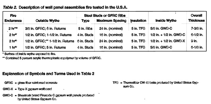
It should be noted that the tests were conducted in accordance with ASTM E119, which requires hose stream tests in addition to fire resistance tests.
Joint Treatments
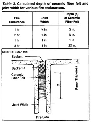
Joint Treatments One-Stage Butt Joints: One of the assemblies listed in Table 2 consisted of GRC panels with 1-1/2 in. (38 mm) returns. In that assembly, the joints were 3/4 in. (19 mm) wide, but instead of using ceramic fiber felt to fires top the joints (Table 3), a 5-in. (127 mm) thickness of TFB insulation (Fig. 11) was placed between the steel studs across the backs of the returns. The same insulation was used between the other studs in the assembly.
The joints in the assemblies with 6-in. (152 mm) returns listed in Table 2 were 1/2 in. (13 mm) wide and were protected with a 5-in. (127 mm) initial depth of the same TFB insulation as that used in the assemblies.
Load Factors and Combinations
Gravity Load Effects: Gravity loads associated with the weight of GRC panels. Three-dimensional panels, often do not result in pure in-plane stresses. Skin bending stresses associated with gravity loads should be considered in design. see the above.
GRC uses strength design concepts - where both the material strength and the loads are factored. Minimum service loads stated in the governing building code, along with the additional load conditions and considerations stated in this recommended Practice, should be considered when assessing various load combinations. The following load factor combinations should be considered as minimums:
0.75 [1.4 D + 1.7 L + 1.7 (greater of W or 1.1 E)]
0.9 D + 1.3 (greater of W or 1.1 E)
1.4 D + 1.7 (greater of M or T)
0.75 [1.4 D + 1.7 (greater of L, W or 1.1 E) + 1.6 (greater of M or T)]
where:
D = dead load
E = earthquake load
L = live load
M = effects of moisture change
T = effects of temperature change
W = wind load
The first four load factor combinations are the same as in ACI 318. For cladding panels there is seldom a live load, however window washing procedures may be a consideration, but would probably not occur with higher wind load.
The factor for moisture and temperature is greater than in ACI 318 due to the uncertainties in values and calculation procedures, and the potential effect if underestimated. If there is a reasonable probability of a higher volume change effect due to a combination of the two, especially initial drying shrinkage and temperature, that is greater than either maximum alone, judgment may indicate that a combination be used. In some circumstances, creep can reduce these effects, but the rates at which moisture and temperature changes and creep occur are difficult to define.
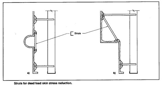
Gravity and Seismic Anchors
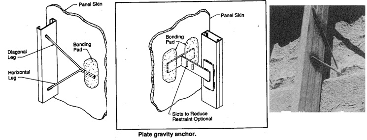
(Refer to accompanying diagram for structural anchoring methodologies and gravity stress distributions on GRC paneling.)
Surface Finishes
Many types of surface finishes successful with architectural precast concrete will be acceptable on GRC panels. The absence of large coarse aggregate in the GRC mix allows it to follow closely the surface texture or pattern of the mould and a wide variety of surface patterns and textures can be provided. It is advisable to avoid sharp angles and thin projections whenever possible and incorporate chamfers or radii at inside corners of the form due to the possibility of fiber bridging.
Combination finishes involving the use of more than one basic finishing method are almost infinite. A demarcation feature or a skin joint should be incorporated into the surface of a GRC panel having two or more different mixes or finishes. The different face mixes shall have reasonably similar behaviour with respect to shrinkage in order to avoid cracking at the demarcation feature due to differential shrinkage.
The cement matrix also offers a wide choice of colour variations through the use of white, grey or buff-coloured portland cements or through the use of colour pigments. It should be noted that colour variation between panels will be directly proportional to the colour intensity. The darker the colour the greater the colour variation.
Sample panels of adequate size may be necessary to translate design concepts into realistic production requirements. With any integral or attached finish material, and its attachment, consideration must be given to the thermal and moisture-induced volume changes and the compatibility of the volume changes or stresses with the aged properties of the GRC.
The fine particle size of the cement-sand slurry matrix allows it to closely follow the surface texture or pattern of the mould. However, the extent to which the glass fibers are able to penetrate surface detail depends on the scale of the detail. The surface layers of a heavily textured panel may consist of un-reinforced cement/sand mortar or they may be exposed aggregate concrete.